Inspection items of water tank and foam fire truck inspection of water tank / foam fire truck
1) Power matching
When the fire pump equipped with the water tank / foam fire truck works under the rated working condition, the ratio of the shaft power of the pump to the rated power of the chassis engine shall meet the following conditions:
When the chassis adopts gasoline engine, the power ratio of the two shall not be greater than 55%.
② When the chassis adopts diesel engine, the power ratio of the two shall not be greater than 60%.
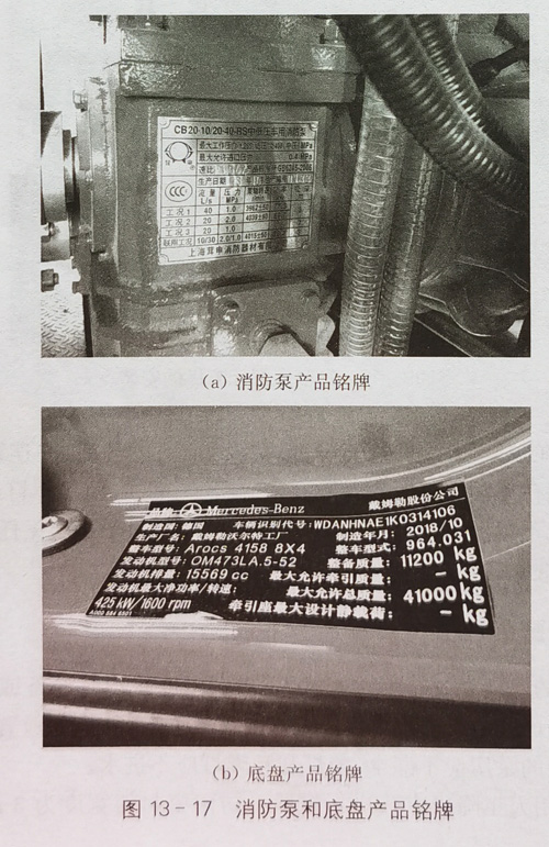
The shaft power of the fire pump under rated working conditions can be found on its nameplate or in the test report of the fire pump; The rated power of the engine can be found in the chassis nameplate, chassis certificate or chassis conformity certificate, as shown in Figure 13-17.
2) Operation panel
The operation panel of water tank / foam fire truck shall generally include the following contents:
① Rated flow and outlet pressure of fire pump and operating instructions.
Display of outlet pressure of fire pump (accuracy not lower than level 2.5). Display of inlet pressure of fire pump (accuracy not lower than level 2.5). Fire pump speed display and cumulative working time display. Liquid level or liquid volume display of water tank / foam tank.
Engine water temperature display.
Instrument panel lighting and switches.
)Use instruction board of instruments and switches on the panel.
⑨ Schematic diagram of water pipeline system and basic operation instructions. Emergency stop button.
In addition, the operation panel of the foam fire truck shall also include the category and mixing ratio of the selected foam, flushing identification and switch position.
3) Maximum vacuum degree and sealing test
When the atmospheric pressure is 101 kPa, the maximum vacuum that can be formed by the water diversion device of the fire truck shall not be less than 85 kPa.
Under the maximum vacuum, the decrease value of vacuum degree within 1 min shall not be greater than 2.6 kPa.
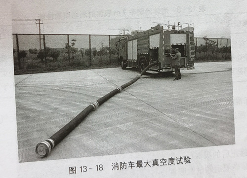
Inspection method: close one end of the suction pipe of the specified length equipped with the foam fire truck and connect the other end to one water inlet of the fire pump to close the other water inlets. There shall be no water left in the fire pump and suction pipeline. Start the water diversion device to the maximum vacuum degree, record the value after it is stable, then close the water diversion device, measure the decrease value of vacuum degree within 1 min, and judge whether the test results meet the requirements of the standard, as shown in Figure 13-18.
It should be noted that during the maximum vacuum and tightness test, if the inlet pressure gauge still fails to reach the specified value or the vacuum value will not rise after the water diversion device operates for a long time (more than 1 ~ 2 min), the test shall be stopped immediately, check whether all valves, including the cooling water valve and residual water of the power take-off, are closed, and confirm whether the tightness of the suction pipe has an impact on the test results.
4) Performance requirements of fire pump at diversion time and maximum suction depth
When the atmospheric pressure is 101 kPa and the water temperature is 20 ℃, the maximum suction depth of the foam fire truck shall not be less than 7 M.
(1) The water diversion time is for different fire pump flows. When the foam fire truck is at the maximum suction depth, the water diversion time shall meet the requirements of table 13-8.

Test method: park the foam fire truck on a flat and hard ground. One end of the equipped suction pipe is connected to the water inlet of the fire pump, and the other end is connected to the water filter. Put it into the pool or other water sources. When the atmospheric pressure is 101 kPa and the water temperature is 20 ℃, the rotation center of the fire pump blade is 7m above the water surface (the water filter must be completely submerged in the water). Start the water diversion device and measure the time from the start of the water diversion device to the pressure displayed on the pressure gauge at the outlet of the fire pump.
(2) The performance of the fire pump at the maximum suction depth. At the maximum suction depth, the flow and outlet pressure of the fire pump shall meet the requirements of table 13-9.

It can be seen from equation (13-5) that the suction depth of the fire pump is corrected according to the on-site environmental conditions of the test site to determine the verticality from the fire pump center to the test water source. If the current suction height is greater than the correction value, it can be supplemented through the water replenishing device; if it is less than the correction value, it can be discharged through the fire pump or submersible fire pump.
In order to ensure the layout of multiple water inlets of large flow fire pump and prevent insufficient suction depth from affecting the test effect, the actual depth of 7m suction well (the height from the bottom to the ground) > 9m, and the inner diameter of the well ≥ 2.
5) Requirements for continuous operation of foam car
The foam fire truck shall be subject to 6h continuous operation test, and the distribution of each working condition is as follows:
① The foam truck equipped with a low-pressure pump shall work continuously for 3h under the rated working condition. It shall continue to work continuously for 3h under the condition that the flow is 70% of the rated value and the outlet pressure is not less than 130% of the rated value.
② The foam car equipped with medium and low pressure pump shall operate continuously for 3h under the low pressure rated condition and continue to operate continuously for 3h under the medium pressure rated condition.
③ The foam car equipped with high and low pressure pump shall operate continuously for 3h under the low pressure rated condition and continue to operate continuously for 3h under the high pressure rated condition.
④ The foam car equipped with medium pressure pump or high pressure pump shall work continuously for 6h under its rated working condition.
During the 6h continuous operation test, the flow and pressure of the fire pump shall meet the specified requirements; The engine speed shall not exceed the rated speed of the engine; The temperature of the power output device shall not exceed 100 ℃ during the continuous operation test: the engine shall not have abnormal phenomena such as abnormal sound, water leakage, oil leakage and air leakage.
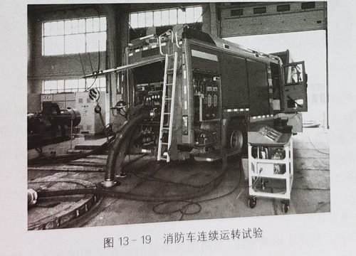
Test method: the foam fire truck is parked on a flat and hard ground. Under a suction depth of 3 m, connect the suction pipe connected with the water filter to the inlet of the fire pump and put it into the water. Start the engine and connect the fire pump, and operate according to the specified working conditions and time, as shown in Figure 13-19. The test process shall not be interrupted, and the outlet pressure and flow of the fire pump shall not be lower than the specified value. When the test conditions are not standard environmental conditions, the water absorption depth shall be corrected. In addition, in order to meet the long-term operation water demand of large flow fire pump, the actual depth of 3M deep suction pool (the height from the bottom to the ground) ≥ 4 m · the capacity of pool ≥ 150 m.
During the continuous operation test, when the water inlet of the fire pump is set on the side, the water inlet shall be set on both sides of the vehicle, and the water inlet on one side shall meet the requirements of the rated pressure and flow of the fire truck.
From the water diversion time of the above foam fire truck, the performance of the fire pump at the maximum suction depth and the continuous operation of the foam truck, it can be seen that the hydraulic performance test of the fire truck has strict requirements on the suction height. Different suction depth conditions produced by different suction height directly affect the test results. Therefore, it is necessary to collect the air pressure and water temperature of the test site through the environmental parameter sensor, and correct the suction height appropriately.
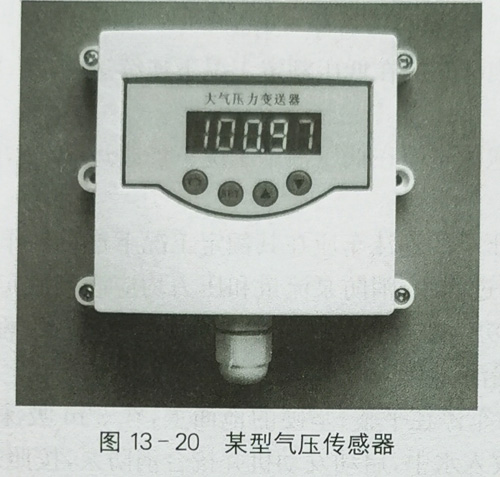
(1) The ambient air pressure of the test site of the air pressure sensor is an important parameter in the correction of suction depth. In order to make use of the space, the wall mounted intelligent barometer can be used, which is externally hung on the outer wall of the monitoring area and has its own digital display function. The air pressure signal can also be transmitted to the control cabinet through the trunking for display. A certain type of air pressure sensor is shown in Figure 13-20.
(2) The water temperature of the water source used for the test of the water temperature sensor is also an important parameter in the suction depth correction. The water temperature sensor must be in contact with the water source, so it should be set and effectively fixed in 3M water tank and 7m water well respectively. At the same time, since the water temperature sensor must be immersed in water for a long time, the corrosion resistance and reliability must be high. A certain type of water temperature sensor is shown in Figure 13-21.

According to the different flow of fire pump, the test pipeline shall adopt multiple different diameters to adapt to different flow ranges. Considering the applicability, economy and foresight of the test pipeline, three test pipelines can be set according to DN50, DN100 and DN200, and the applicable nominal pressure of the pipeline can be determined according to the pressure level corresponding to the flow of the fire pump. In addition, the of each test pipeline shall also be designed according to the installation requirements of the flowmeter. Generally, the front and rear ends of the flowmeter are required to be straight pipe sections, and the length of the front end shall not be less than
5 times of the pipeline diameter, and the length of the rear end shall not be less than 3 times of the pipeline diameter. The specific setting shall also be carried out according to the installation requirements of the flowmeter, as shown in Figure 13-22.
6) Fire monitor spraying performance
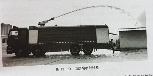
(1) Test conditions the fire water monitor and foam / water dual-purpose monitor shall be sprayed on a flat site, as shown in figure 13-23

As shown in. During the test, a pressure gauge shall be installed at the water inlet of the fire monitor, and the accuracy of the pressure gauge shall not be lower than grade 1.6. The elevation angle of the fire monitor shall be 30 ° + 1 °, and the wind speed shall be less than 2m / s. During the test, when the water inlet pressure of the fire monitor reaches the rated working pressure and is stable, use a stopwatch to measure the concentration point of continuous sprinkling water for no less than 10s as the farthest point of range, take the intersection of the plumb line of the fire monitor outlet and the ground as the origin, and the linear distance between the farthest point and the origin is the range of the fire monitor. In order to ensure accurate measurement, spray twice and take the average of the two ranges.
(2) Performance parameters the rated working pressure, range and other corresponding performance parameters of fire water monitor and bubble / water monitor shall comply with the provisions of table 4-8, table 4-9 and table 4-10 respectively:
(3) The mixing ratio of foam is determined by refractometer. The mixing ratio of foam is obtained by looking up the table. The specific methods are as follows:
① Take out the test foam solution with a burette, and drip 3m6ml and 9ml into three 100ml measuring tablets respectively Foam liquid. Then add 100ml of test water to make foam mixture with 3%g% and 9% standard concentration. After full mixing, read the scale value on the refractometer respectively, and make the calibration curve between the refractometer's degree and the concentration of foam solution on the coordinate paper.
② Take the precipitated liquid as the test sample, read the scale number 3 of the sample on the refractometer, and check the mixing ratio of the sample from the calibration curve.


